3k3y installation guide into a PS3 SuperSlim

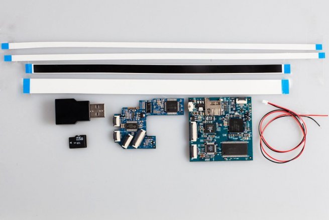
Hi everybody, we are going to develop an installation guide for 3k3y ( available on the LS store at this address and will be available for shipping via DHL within 24H ).
3k3y PS3 400x installation manual :
1. Remove the main PCB from your PS3 Superslim. Locate the four SATA bus capacitors
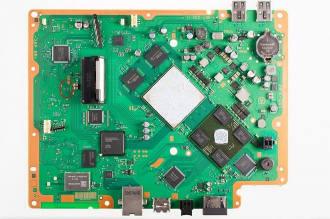
Illustration 1 : Locate The Four SATA Bus Capacitors
The SATA Bus Capacitors are circled in red
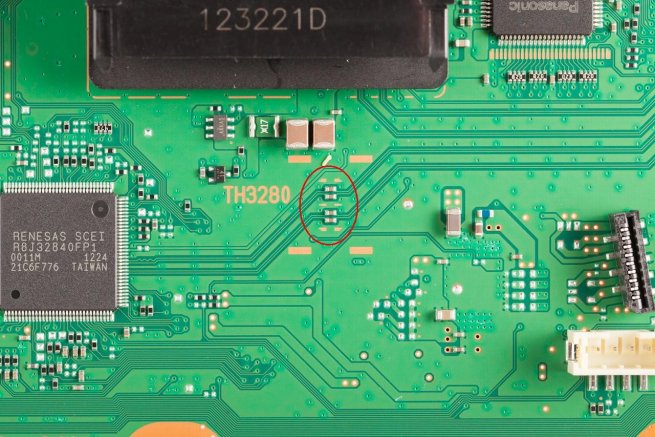
Illustration 2 : Close Up Of The Four SATA Bus Capacitors
2. Remove the SATA bus capacitors
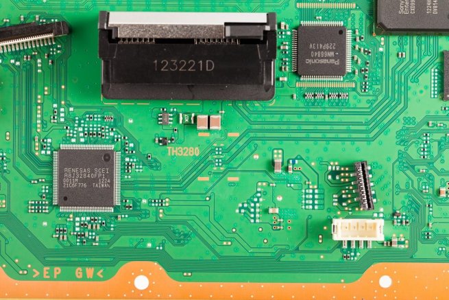
Illustration 3 : Remove The Four SATA Bus Capacitors
3. Fit the 3K3Y Super Slim adapter to the PS3 PCB
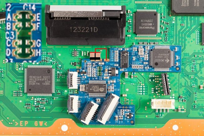
Illustration 4 : Install the 3K3Y Adapter
Center the cut out in the 3K3Y adapter over the pads for the SATA Bus capacitors.
Align the pads with the solder points A-H. When you are satisfied with the alignment solder the GND pad to the adjacent capacitors (black line)
- Solder points A-H to their respective SATA Bus capacitor pads.
- Solder a wire from the 5V pad to the top of the two capacitors (red line)
- Solder the 3K3Y main PCB power cable to the 5V (red wire) and GND (black) pads
- Solder a wire from the LID point on the adapter to the centre pin of the cover switch connector
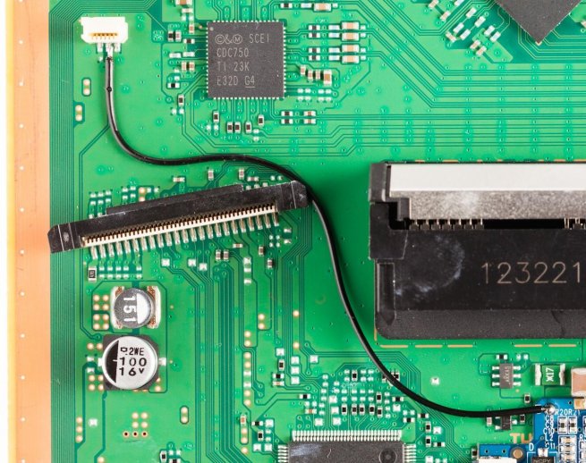
Illustration 5 : Wire from LID Point to Cover Switch Connector
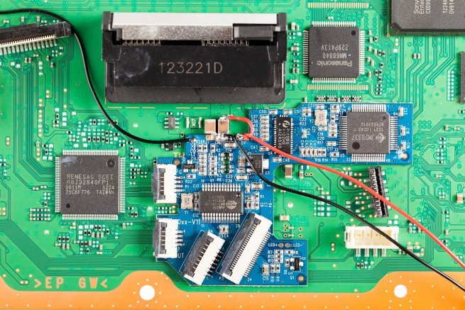
Illustration 6: Soldering Complete
4. Install The FFCs
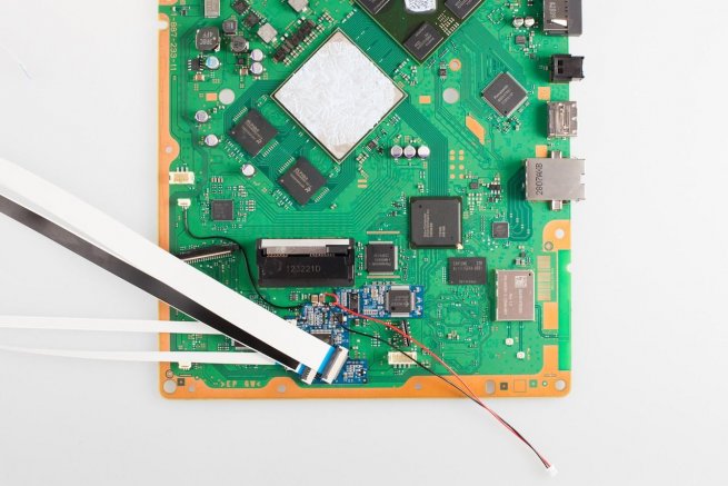
Illustration 7 : Fit The FFCs
- Fit the longest 4 way FFC to the ZIF connector labelled OUT
- Fit the shortest 4 way FFC to the ZIF connector labelled 3KS
- Fit the 24 and 7 way FFCs
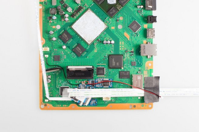
Illustration 8 : Fold The FFCs
Fold the FFCs as shown
5. Refit The HSF & Top Shielding
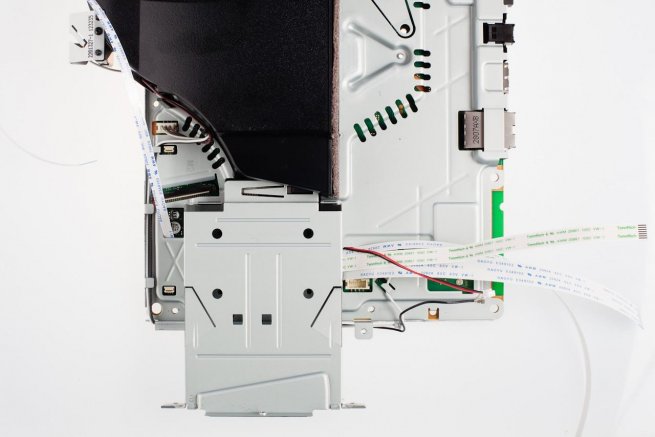
Illustration 9 : Refit The HSF & Top Shielding
Route the FFCs out of the cutouts as shown take care not to pinch the FFCs.
Reconnect the fan power cable & the RF cables
Refit the bottom shield and retaining screws
6. Route the USB FFC Out of the PS3's case
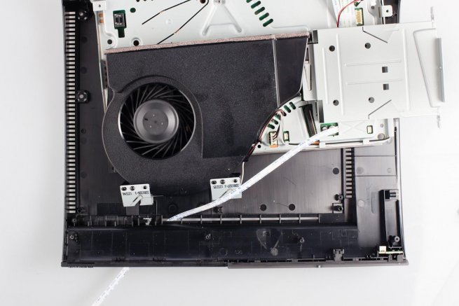
Illustration 10 : Route the USB FFC
Feed the USB FFC out of the case through a ventilation slot.
7. Insulate the PS3 Metalwork
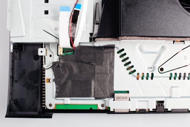
Illustration 11 : Insulate the PS3 Metalwork
Cover the metal shield with an insulating material.
Testing :
Before fully reassembling your PS3 it is a good idea to test your installation.
The 3K3y FFCs are long enough to allow the PS3 to be reassembled while still allowing access to the 3K3y main PCB.
Replace the PS3 PSU, power switch, cover switch and BD drive mechanics.
Tape the cover switch in the down position, this simulates the cover in the closed position.
Power up the PS3 and observe LED1. See Appendix A for an explanation of the diagnostic codes.
- If the 3K3y indicates Passthru mode check the cover switch is taped down correctly and repeat the test.
- If the 3K3y indicates Emulation mode then the installation has been successful.
8. Install the 3K3Y main PCB
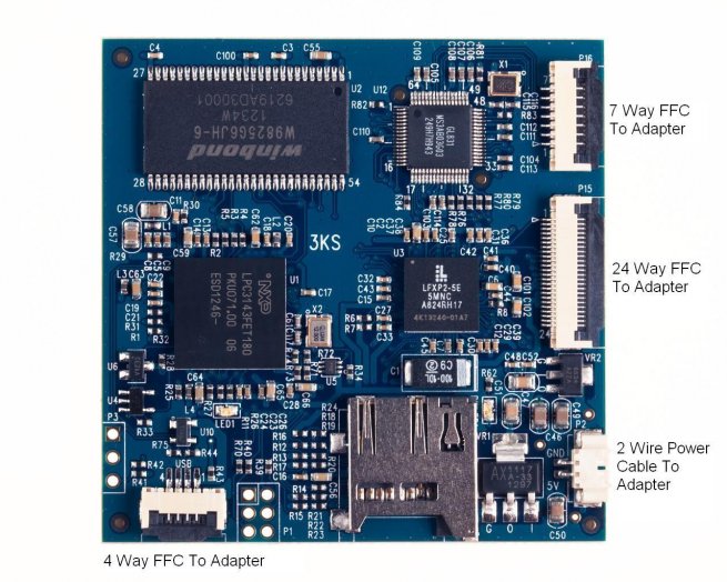
Illustration 12 : 3K3y Connectors
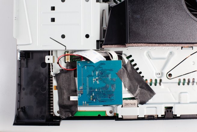
Illustration 13 : Install The 3K3Y PCB
9. Modify the PSU Plastic
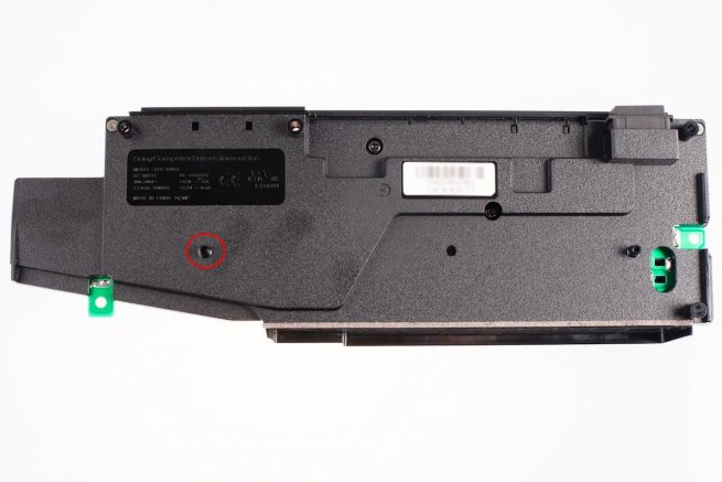
Illustration 14 : Modify The PSU Plastic
With a sharp knife, remove the plastic peg circled in red.
10. Reassemble the PS3
Replace the PS3 PSU, BD drive sled & plastic top cover.
11. Fit the USB Adapter
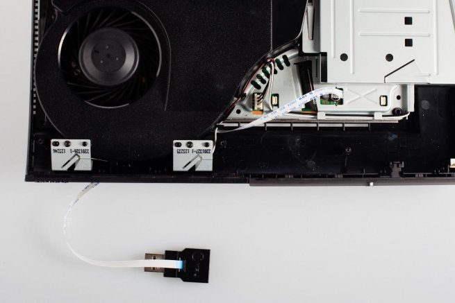
Illustration 15 : Fit the USB Adapter
Insert the 4 way FFC into the USB adapter making sure the blue reinforcement plastic is facing towards the female end of the adapter.
Plug the adapter into one of the PS3's USB port
Appendix A
The 3K3y will display diagnostic information by flashing LED1.
After 90 seconds the 3K3y diagnostics will be stable and can be interpreted as follows :
Slow Flashing : SD card incorrectly seated : reintroduce the SD Card
Fast Flashing : Detecting PS3 drive controller : Check solder points A-D
Solid : Waiting for PS3 : Check solder points E-H
1 flash : 3K3y is in Passthru mode
2 flashes : Bad FPGA/FPGA Version : Update the FPGA
3 flashes : Bad BD : Check solder points A-D
4 flashes : Bad D1 : Update the 3Key.cfg with a valid D1
5 flashes : 3K3y is in Emulation mode
@++